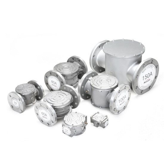
HGF 2115 / 2120 / 2125 / 2140 / 2150
HGF 2150F / 2165F / 2180F / 21100F / 21150F
|

|

|
According to Pressure Equipment Directive 97/23/EC
Rating : Class I , 1000mbar, -20~60℃
|
|
|
HGF 2115 / 2120 / 2125

|

|
|
HGF 2140 / 2150

|

|
|
HGF 2150F / 2165F / 2180F / 21100F
 
 
|
|

|
DIMENSION & TECHNICAL SPECIFICATION
|
MODEL
|
A
|
B
|
C
|
D
|
E
|
H
|
L
|
Weight (Kg)
|
|
HGF 2115 (15A)
|
Rp 1/2"
|
65
|
-
|
-
|
-
|
40
|
110
|
0.65
|
|
HGF 2120 (20A)
|
Rp 3/4"
|
65
|
-
|
-
|
-
|
40
|
110
|
0.62
|
|
HGF 2125 (25A)
|
Rp 1"
|
75
|
-
|
-
|
-
|
40
|
110
|
0.63
|
|
HGF 2140 (40A)
|
Rp 1" 1/2
|
83
|
-
|
-
|
-
|
46
|
160
|
1.24
|
|
HGF 2150 (50A)
|
Rp 2"
|
83
|
-
|
-
|
-
|
43
|
160
|
1.31
|
|
HGF 2150F (50A)
|
DN 50
|
83
|
125
|
17
|
160
|
70
|
215
|
3.47
|
|
HGF 2165F (65A)
|
DN 65
|
152
|
160
|
17
|
194
|
56
|
312
|
5.29
|
|
HGF 2180F (80A)
|
DN 80
|
152
|
160
|
17
|
194
|
56
|
312
|
6.06
|
|
HGF 21100F (100A)
|
DN 100
|
192
|
180
|
18
|
216
|
85
|
316
|
8.81
|
|
HGF 21150F (150A)
|
DN 150
|
304
|
240
|
22
|
287
|
160
|
491
|
19.86
|
GENERAL SPECIFICATION
|
Working gas
|
LNG(Town gas), LPG, Air, Flue gas, Non-aggressive gas
|
|
Ambient temperature
|
-20 ∼ 60 ℃
|
|
Miximum inlet pressure
|
6 bar
|
|
Testing Max. pressure
|
25 bar
|
|
Filtering
|
≤ 50um
|
MATERIALS
|
Housing base
|
Aluminium diecast
|
|
Seals
|
NBR
|
|
Filter pad
|
Nonwoven polypropylene fabric & Aluminium mesh
Nonwoven polypropylene fabric & PVC Cartridge
|
■ EXCHANGE FILTER CARTRIDGE
- In order to maintain the capacity of the filter, filter cartridge must be replaced once the at least one year.
- Even if not a year, if pressure difference between the two sides of the filter increased more than 50%
depending on the fluid, it must be replaced.
■ INSTALLATION
- Filters should be installed in vertical or horizontal piping.
- The housing cover should be detachable at the side so that no dirt gets into the housing during maintenance.

■ ATTENTION
All installation/maintenance work must be carried out by skilled staff. Always check that the system is gas-tight after installation.
Failure to follow this manual can result in dangerous situations or damage to the product.
■ INSTALLATION
1. Warning
- The gas supply must be shut off before installation.
- Do not remove the plugs before installation.
- During installation take care not to allow debris or scraps of metal to enter the device.
- The arrow on filter housing must be matched to gas flow direction.
2. Installation Location
- Installs in a position to remove the lid for Inspection, cleaning or change filtering net.
- It should be installed at least 30mm away from hot objects or wall.
3. Threaded connections
- overlong threads may damage the body of the device when screwed into place.
4. Flanged connections
- The inlet and outlet counter flanges are perfectly parallel to avoid unnecessary mechanical stresses on the
body of the device.
- Also calculate the space needed to fit the seal. After placing a gasket between the filter and the flange, fix the filter.
It can fill some lubricant (Grease), if necessary.
■ MAINTENANCE
- If pressure difference has increased by 50% compared to new filtering net.
Please replace it with a filtering net at least once a year.
■ EXCHANGE FILTER CARTRIDGEE
1. The gas supply must be shut off before installation.
2. Make sure that there is no pressurised gas inside the device before remove cover.
3. Unscrew the fixing screws and disassemble the filtering net.
4. Re-assemble filtering net in the original position checking that it is properly positioned in the guides and
check that it does not prevent assembly of the cover.
5. After installation, perform leak test. (Soapy water test)