|
GENERAL SPECIFICATION
|
Working gas
|
LNG(Town gas), LPG, Air, Flue gas,
Biologically produced Methane gas
|
|
Working voltage
|
24 ~ 240V
|
|
Ambient temperature
|
-15 ∼ 60 ℃
|
|
Silver standard contact
|
|
|
Switching capacity
|
5A
|
|
Protection grade
|
IP 66
6- Dust tight, No ingress of dust
6- Protection against strong jets of water from all directions.
|
MATERIALS
|
Explosion-proof housing
|
Aluminium diecast
|
|
Internal housing base
|
Aluminium diecast
|
|
Switch
|
Nylon W6
|
|
Hood
|
Polycarbonate
|
|
Diaphragm
|
HNBR
|
|
Pressure connection
|
Stainless steel
|
TECHNICAL SPECIFICATION
|
MODEL
|
Adjusting Range
|
Switching DIfference ΔP
|
Max. Operating Pressure
(mbar)
|
Adjusting Tolerance
|
Pressure Control Range
|
|
EX-HSG 3003
|
0.4~3.0 mbar
|
≤ 0.4 mbar
|
500 mbar
|
±15%
|
0.5 ~ 500 mbar
|
|
EX-HSG 3050
|
2.5~50 mbar
|
≤ 1 mbar
|
|
EX-HSG 3150
|
30~150 mbar
|
≤ 4 mbar
|
|
EX-HSG 3500
|
100~500 mbar
|
≤ 30 mbar
|
APPLIANCE
Explosion-proof box of this product has received safety certification from Korea Gas Safety Corporation to
produce and mount a 3rd party pressure control (pressure switch) at the request of the consumer.
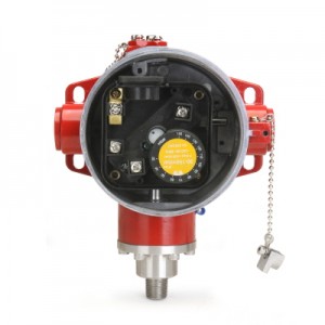
TECHNICAL DESCRIPTION

□ Pressure connections
A or B : For excessive pressure
C or D : For negative pressure
Use yellow scale wheel to adjust the spring to the switching pressure.
The pressure in the controlled line has an effect on the diaphragm which opens and closes
against the spring force of the microswitch.
■ APPLICATION
It can be applied in various ways depending on the installation sequence in accordance with the other devices,
and it must be performed by the following tests.
- Excessive pressure test : If connecting excess pressure to connection A or B, it must be ventilated via connection C or D.
- Negative pressure test : If connecting negative pressure to connection C or D, it must be ventilated via connection A or B.
- Differential pressure test : If connecting the higher pressure to connection A or B, remaining connections must be plugged.
■ INSTALLATION POSITION
 [ Standard installation position ] [ Standard installation position ]
Install the standard position as shown.
[Figure1] is available but the switching point is made in other place.
The installation of other positions including [Figure2], [Figure3] is impossible.
|

[Figure1]
|

[Figure2]
|

[Figure3]
|
■ ATTENTION
All installation/maintenance work must be carried out by skilled staff.
Always check that the system is gas-tight after installation.
Failure to follow this manual may result in dangerous situations or damage to the product.
■ TECHNICAL DESCRIPTION
- Diaphragm type pressure switch can be used in a variety of process lines.
- This product is a mechanical pressure control without auxiliary power.
■ INSTALLATION
1. Warning
- Select a product based on the operating pressure depending on the model specifications table
in this manual before installation.
- All the gas supply must be shut off before installation.
- Make sure that the pipeline is free from impurities and vibration before installation.
- Caution to prevent ignition of hazardous atmospheres turn off power before opening.
- Close the cover tightly before operation.
- Function and holding tests must be carried out after installation.
2. Installation Location
- Installs in a standard installation position presented in this manual
- Change of the switching point may occur if installation position differs from standard.
■ ADJUSTMENT
1. Remove the transparent cover by meaning of across screwdriver.
2. Turn the yellow range scale adjustable knob to achieve the nominal pressure worth.
3. The differential pressure acts on the micro switch via the diaphragm against the force of the adjusting spring.
■ Standards and specifications of this product are subjective to change without prior notice for improved performance.
|