
|
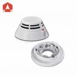
| Addressable Smoke Detector:CFT-930 | |||||||||||||||||||||||||||||||||||||||||||||
|
|||||||||||||||||||||||||||||||||||||||||||||
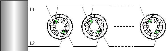
2. Wiring method: The detector is accessed through a compatible fire alarm control panelvia a two-wire bus. It uses non-polarity connection. The terminals L1 and L2 ofthe two-wire bus are connected with the terminals 1 and 3 of the matchedmounting base. Fig.3 is a schematic diagram of the connection between multipledetectors with a fire alarm control panel.
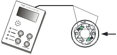
Fig.3 3. Codingaddress: As shown in Fig.4, detector is accessed via the detector mounting baseon the coder, non-polarity connection is adopted for the terminals L1 and L2,set the coder with the coding function, select the correct address number andpress the RUN key to complete the address code setup. (Note: See the User’sManual of the coder for the detailed operation.)
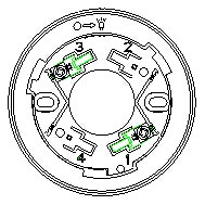
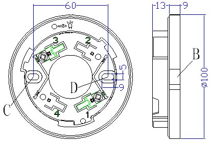
Fig.4 VI. Installation and debugging Determine thelocation, mounting distance and numbers for mounting the detectors in theprotection area according to relevant provisions and regulations of GB50116-98 Code for Design of Automatic Fire AlarmSystem and GB50166-2007 Code forInstallation and Acceptance of Fire Alarm System. A self-contained complete base is necessary during theinstallation of a detector. As shown in Fig.5, the model, the externaldimensions, the mounting hole diameter and the mounting hole spacing of thebase are DZ-910, 100mm×22mm (diameter×thickness), 5mm and 56mm~64mmrespectively.
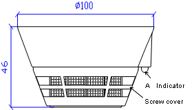
Fig.5 Wiring requirement: It isproper to use RVS twisted pairs with a section area of equal to or larger than 1.0mm2 for the signal buses L1 andL2. Specific installation and debuggingmethods: 1. Makesure the type of the detector matches the type of the host machine of the firealarm control panel; 2. Usetwo M4 screws to fix the matched mounting base on the designated position viathe mounting holes C and D shown in Fig.5, as instructed in the constructiondrawing and make sure the matched mounting base has been firmly installed. 3. Usea coder to make the detector coded according to the detector address on theconstruction drawing. 4. Disconnectthe power supply of the fire alarm control panel and connect the detectorcorrectly according to the construction drawing. 5. Placethe indicator at position A of the detector (see Fig.1) and position B of thebase (see Fig.5), align them with each other, insert the detector into the baseand turn the detector clockwise until it is firmlylocked. 6. Afterall the products are installed and checked, connect the power supply of the firealarm control panel and conduct automatic login. 7. Whenautomatic login is success, the red indicator of the detector will blink onceabout every 12 seconds, which suggests that the detector has begun to operatenormally. 8. Finallyconduct an alarm test for the detector through some special tools or directsmoke blowing. After the detector gives a fire alarm, the indicator will remainlit and the fire alarm control panel will simultaneously show correspondingalarm prompt information. After the alarm test, reset the fire alarm controlpanel and restore to the monitoring status. VII. Precautions 1. Adetector can not share an address with other equipment in a single bus circuit,or else an address conflict may occur. 2. Neverdismount the protective cover delivered with the detector too early after thefield installation and before the use of the detector, or else the detector maybe contaminated. 3. The protection area andquantity of the detectors should comply with relevant provisions in GB50116-98 Code for Design of Automatic Fire AlarmSystem and GB50166-2007 Code forInstallation and Acceptance of Fire Alarm System. VIII. Maintenance Warning: Before conducting maintenancefor detectors, informtherelated management department that the monitoring will be stopped temporarilywhen the system maintenance. Meanwhile, disable the logic control function ofthe area or system to be maintained to avoid unnecessary alarm linkage. Afterthe test, inform the management department to restore the normal functions ofthe system. 1. For adetector, at least semi-annual tests should be done according to relatedprovisions of GB50166-2007 Code forInstallation and Acceptance of Fire Alarm System; for a detector that hasbeen installed and used, it is recommended to haveit cleaned and maintained once every two years. 2. Operatingenvironment has a great influence on the performance of the detector. If thedetector is installed and used in a placewhere its normal use is easily affectedby dust, high wind speed and other factors, its maintenance period should beshortened. 3. If adetector fails due to a material defect or a manufacturing process defect undernormal conditions of use in one year following the date of its delivery, weshall repair or replace it for free. However, the faults of the detector due toartificial damage, improper use, or authorizedadjustment, reconstruction or disassembly are not coveredin the guaranteeand we shall assume no responsibilities for any theconsequence thereby caused. 4. We mayprovide paid repair service for products with any faults beyond the guaranteerange. If you have such products that need repair,please contact us. When sending such a product to us for repair, you areexpected to provide some important information about the product, such as thephenomenon and possible cause of the product fault, so that we can find out thecause of the fault in the shortest time and so theinformation may be used as a reference in our future product development andimprovement. IX. Fault analysis and troubleshooting
ไม่พบวีดีโอ
ไม่พบไฟล์
สินค้าใกล้เคียง
|
|
|
|