
|
| Addressable Heat Detector:CFT-920 | ||||||||||||||||||||||||||||||||
|
||||||||||||||||||||||||||||||||
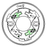
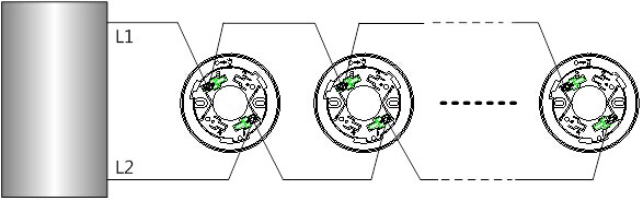
2. Wiringmethod: The detector is accessed through a compatible fire alarm control panelvia a two-wire bus. It uses non-polarity connection. The terminals L1 and L2 ofthe two-wire bus are connected with the terminals 1 and 3 of the matchedmounting base. Fig.3 is a schematic diagram of the connection between multipledetectors with a fire alarm control panel.
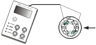
Fig.3 3. Codingaddress: As shown in Fig.4, detector is accessed via the detector mounting baseon the coder, non-polarity connection is adopted for the terminals L1 and L2,set the coder with the coding function, select the correct address number andpress the RUN key to complete the address code setup. (Note: See the User’sManual of the coder for the detailed operation.)
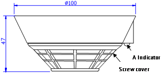
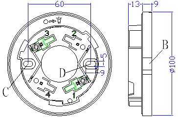
Fig.4 VI. Installation and debugging Determinethe location, mounting distance and numbers for mounting the detectors in theprotection area according to relevant provisions and regulations of GB50116-98 Code for Design of Automatic Fire AlarmSystem and GB50166-2007 Code forInstallation and Acceptance of Fire Alarm System. A self-containedcomplete base is necessary during the installation of a detector. As shown inFig.5, the model, the external dimensions, the mounting hole diameter and themounting hole spacing of the base are DZ-910, 100mm×22mm (diameter×thickness), 5mm and 56mm~64mmrespectively.
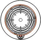
Fig.5 Wiring requirement: It isproper to use RVS twisted pairs with a section area of equal to or larger than 1.0mm2 for the signal busesL1 and L2. Specific installation and debuggingmethods: 1. Makesure the type of the detector matches the type of the host machine of the firealarm control panel; 2. Usetwo M4 screws to fix the matched mounting base on the designated position viathe mounting holes C and D shown in Fig.5, as instructed in the constructiondrawing and make sure the matched mounting base has been firmly installed. 3. Usea coder to make the detector coded according to the detector address on theconstruction drawing. 4. Disconnectthe power supply of the fire alarm control panel and connect the detectorcorrectly according to the construction drawing. 5. Placethe indicator at position A of the detector (see Fig.1) and position B of thebase (see Fig.5), align them with each other, insert the detector into the baseand turn the detector clockwise until it is firmly locked. 6. Afterall the products are installed and checked, connect the power supply of thefire alarm control panel and conduct automatic login. 7. whenautomatic login is success, the red indicator of the detector will blink onceabout every 12 seconds, which suggests that the detector has begun to operatenormally. 8. Finallyconduct an alarm test for the detector through some special tools or direct hotair gun blowing. After the detector gives a fire alarm, the indicator willremain lit and the fire alarm control panel will simultaneously givecorresponding alarm prompt information. After the alarm test, reset the firealarm control panel and restore to the monitoring status. VII. Precautions 1. Adetector can not share an address with other equipment in a single bus circuit,or else an address conflict may occur. 2. Neverdismount the protective cover delivered with the detector too early after thefield installation and before the use of the detector, or else the detector maybe contaminated. 3. It is not permitted to useopen flames (such as lighters) to firing thermistor during alarm tests, so asto avoid damage to the detector. It is recommendedto use a hot airgun and other heating equipment in a simulation alarm test. 4. Theprotection area and quantity of the detectors should comply with relevantprovisions in GB50116-98 Code for Designof Automatic Fire Alarm System and GB50166-2007 Code for Installation and Acceptance of Fire Alarm System. VIII. Maintenance Warning: Before conducting maintenancefor a detector, inform therelated management department that the monitoring will be stopped temporarilywhen the system maintenance. Meanwhile, disable the logic control function ofthe area or system to be maintained to avoid unnecessary alarm linkage. Afterthe test, inform the management department to restore the normal functions ofthe system. 1. Accordingto the requirements of GB50166-2007 Code for Installation and Acceptance of FireAlarm Systems, eachquarter, some special testing instruments should be used to test the detector’soperation and confirm the indication state of its indicators bybatch and stage; for a detector that has been installed and used, It isrecommendedto have it maintained once everytwo years. 2. If adetector fails due to a material defect or a manufacturing process defect undernormal conditions of use in one year following the date of its delivery, weshall repair or replace it for free. However, the faults of the detector due toartificial damage, improper use, or authorized adjustment, reconstruction ordisassembly are not covered in the guarantee and we shallassume no responsibilities for any theconsequence thereby caused. 3. We mayprovide paid repair service for products with any faults beyond the guaranteerange. If you have such products that need repair,please contact us. When sending such a product to us for repair, you areexpected to provide some important information about the product, such as thephenomenon and possible cause of the product fault, so that we can find out thecause of the fault in the shortest time and so theinformation may be used as a reference in our future product development andimprovement. IX. Fault analysis andtroubleshooting
ไม่พบวีดีโอ
ไม่พบไฟล์
สินค้าใกล้เคียง
|
|
|
|