|
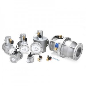
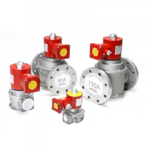
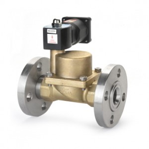
| Manual Reset Type gas safety (shut-off solenoid valve | |||||||||||||||||||||||||||||||||||||||||||||||||||||||||||||||||||||||||||||||||||||||||||||||||||||||||||||||||||||||||||||||||||||
|
|||||||||||||||||||||||||||||||||||||||||||||||||||||||||||||||||||||||||||||||||||||||||||||||||||||||||||||||||||||||||||||||||||||
DIMENSION & TECHNICAL SPECIFICATION - The Manual Reset - Normally Closed Type -
GENERAL SPECIFICATION
MATERIALS
■ TECHNICAL DESCRIPTION
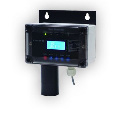
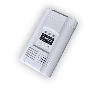
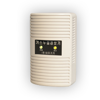
- HGSO series solenoid valve connected to the gas leak detector or alarm signals for the presence of carbon monoxide, is suitable to perform locking operations on the gas line. - While electricity is not flowing, the gas passage is opened by pulling manually reset. - Because of an electrical signal from a gas leak detector, current flows in the coil and the coil pull a support of shutter to block the flow of gas. - The supports is removed, the shutter close the gas passage quickly. (within 1 second) - If energizing of the sensor persists bacause of the presence of gas, the valve remains under power and does not allow reset. - When the cause for locking have been eliminated, valve must be opened manually - HGS series is normally installed downstream a manual shut-off valve and upstream of the gas regulating train.
■ ATTENTION All installation/maintenance work must be carried out by skilled staff. Always check that the system is gas-tight after installation. Failure to follow this manual can result in dangerous situations or damage to the product.
■ INSTALLATION 1. Warning - For proper and safe operation and long service life of the valve, consider the following recommendations of the valve during the design of the system when the valve is installed. · Rated voltage and current · The degree of protection vessel · Dimensions of tolerance parallel thread · Attachment Method · The environment · Pull method · Location inlet section · Using leased lines · Max. Operating Pressure - Shut off the air/gas supply at the main manual shut-off valve and disconnect electrical power to the valve before proceeding with installation or servicing. - Before installation, ake sure that the pipeline is free from impurities and vibration-free. - Solenoid surface may be hot. Do not touch it with bare hands. - The filter must be installed upstream of the solenoid valve for proper operation. - Avoid excessive quantities of sealing agent which could enter in the valve. - Use proper tools only and avoid overtightening. - Make sure all gaskets are used properly. - Please be sure protective measures to prevent easy access to the facilities. - If you do not use the Rated voltage products can cause serious malfunction. - After installation, function and leaking tests must be carried out. - Perform maintenance must be done at least once a year.
2. Installation Location - Ensure that installing area is protected from rain or moisture and sunlight. - It may cause the heat to the coil according to the installation environment. Don’t install the valve in a position close to the wall or another device.
ไม่พบวีดีโอ
ไม่พบไฟล์
สินค้าใกล้เคียง
|
|
||||||||||||||||||||||||||||||||||||||||||||||||||||||||||||||||||||||||||||||||||||||||||||||||||||||||||||||||||||||||||||||||||||
|
|