

|
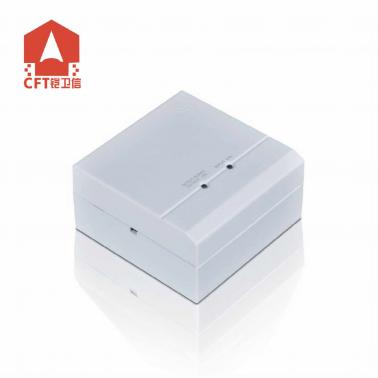
| Intelligent Input/Output Module:CFT-956 | ||||||||||||||||||||||||||||||||||||||||||||||||||||
|
||||||||||||||||||||||||||||||||||||||||||||||||||||
Jumper description (see Fig.1)
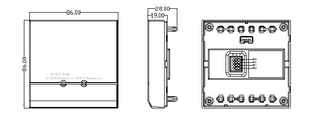
Fig.1 Main Body of the CFT-956 Module
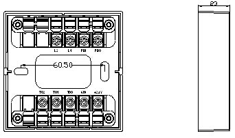
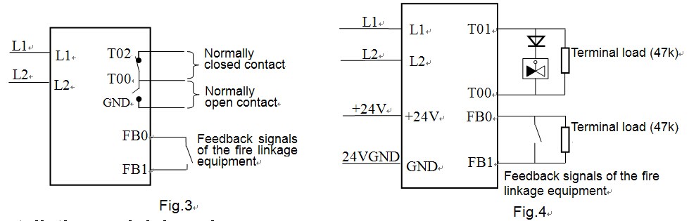
Fig.2 Baseof the CFT-956 Module 12. Wiring method of the KZJ-956 module 1) When a built-in terminal load is used, thewiring method is shown in Fig.3. A dry contact signal (namely a relay contactsignal) is output after action. 2) When an external terminal load is used, thewiring method is shown in Fig.4. It is necessary in this case to have the loadcircuit and the feedback circuit connected in parallel with a 47K terminalload. The KZJ-956 module is able to identify the short or open circuit fault ofthe load circuit and the open circuit fault of the feedback circuit.
IV. Installationand debugging 1. Make sure the type of the module matches thetype given on the construction drawings. 2. Connect the 4-pin coding plug on the coderwith the 4-pin coding socket (see Fig.1) on the main body of the CFT-956 moduleand then set the coder with the coding function and compile the correct addresscode to finish the address coding. 3. Conduct correct wiring as instructed in Fig.3or Fig.4. 4. Use two M4 screws to fix the module base viathe two elliptic screw holes shown in Fig.2 and then insert the main body ofthe CFT-956 module into the module base and make sure they contact each otherwell. 5. After the CFT-956 module is installed andchecked, connect the power supply of the fire alarm control panel. Uponsuccessful login, the inspection indicator of the CFT-956 module will blinkonce about every 12 seconds, which suggests that the CFT-956 module has begunto operate. 6. Conduct debugging after the installation iscompleted. Make the fire alarm control panel send out a starting signal and havethe starting signal sent by the CFT-956 module to the fire linkage equipmentconnected with it. After that, the fire linkage equipment will operatecorrespondingly and the inspection indicator of the CFT-956 module will be lit.The operating fire linkage equipment will give a feedback signal. Afterreceiving the feedback signal, the CFT-956 module will have its input indicatorlit, which suggests that it has begun to operate normally. 7. After the debugging, reset the CFT-956 moduleand related equipment. V. Precautions 1. When an external terminal load is used, donot connect the positive and negative poles of the external 24V power supplyinversely, or the CFT-956 module may be damaged. 2. Do not allow two or more products in a singlecircuit to share the same address, or else the system will report a coincidentcode fault. 3. Confirm the type of the input equipmentconnected with the CFT-956 module (feedback equipment or fire alarm equipment)and have the corresponding equipment type of the CFT-956 module set in the firealarm control panel. After automatic login, the CFT-956 module will treat theinput equipment as fire alarm equipment by default.
ไม่พบวีดีโอ
ไม่พบไฟล์
สินค้าใกล้เคียง
|
|
|||||||||||||||||||||||||||||||||||||||||||||||||||
|
|