What is a Mass Flow Controller?
Principle and sturacture of mass flow controllers.
What is a Mass Flow Controller?
Mass Flow Controllers control the flow rate by measuring mass flow rate of fluid. It is possible to control stable with a high accuracy because it is not required to correct due to change of temperature or used pressure.
Volume flows, such as flow meters and needle valves, are required to correct due to the change of temperature or pressure when they need a certain degree the accuracy flow rate.
Mass flow controllers and mass flow meters have been used for the field of semiconductor and flat panel display that require the high accuracy measurement and control. In addition, they have been used in the wide variety of process such as analysis, fuel cell, a liquid crystal, organic EL, biotechnology, food, environmental measurement, combustion gas control, factory equipment, laboratory equipment.
FCON's Mass Flow Controller / Mass Flow Meter is enhancing performance and reliability by its original technology pursuing basic performance. We aim to design and manufacture products that can be used in a wide range of fields.
Principle and Structure of Mass Flow Controller
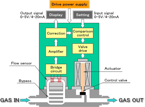
The mass flow controllers are structured from flow sensor, bypass, valve, and the control circuit as shown in the figure below.
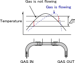
The flow sensor used in mass flow is called a thermal flow sensor in general. The two resistive elements generate heat when electric current flows through these that are wound on the upstream side and the downstream side, around the stainless capillary tube.
When no fluid flows in the capillary tube, the heat of the upstream and downstream sides of the resistive element is the flow rate output signal is maintained in equilibrium state indicates zero.
Gas from the entrance is divided into a sensor and a bypass. When the fluid begins to flow to the sensor, a temperature difference arises between the upstream and downstream sides. This change has been pick up as a flow rate output signal by the bridge circuit. Compare with the flow rate output signal, the external flow setting signal and the flow signal output from the sensor, respectively, the flow control valve to operate the PID for matching the signal level. By this system fine-tunes the valve automatically, permits stable mass flow control under setting condition.
 |
 |
|
■Structure of Mass Flow Controller |
■Temperature distribution of Flow Sensor |
Conversion factor
|
Conversion factor is a number which represents the change in flow rate displayed by the type of gas. Generally, (N2) is a reference (1). |
e.g. Flow O2 to the calibrated Mass Flow Controller with He. How much the actual flow rate of O2 when it is displayed with 100ccm?
Actual flow rate of O2 = a number of display × (C.F of gas/C.F of mass flow controller) = 100 × (0.99/1.40) = 70.71ccm |
|
● The public standard CF should be used for reference only. |
|
Gas type |
C.F |
Gas type |
C.F |
|
N2 (Nitrogen) |
1.00 |
Air |
1.00 |
|
He (helium) |
1.40 |
CO (Carbon monoxide) |
1.00 |
|
H2 (Hydrogen) |
1.00 |
CO2 (Carbon dioxide) |
0.74 |
|
O2 (Oxygen) |
0.99 |
NO (Nitric oxide) |
0.99 |
|
Ar (Argon) |
1.40 |
C2H2 (Acetylene) |
0.70 |
● Mass Flow Controller is basically adjusted the gas type and flow rate that specify by customers. In case using the other gases, Calculated value by C.F and the actual flow rate may not match. In addition, it may cause abnormal operation or abnormal flow by the differences in the physical properties values of the gas.
● It has also been selling multi-gas multi-range (MG / MR) mass flow controller in response to several kinds of gas and flow rate.
● If you use other gases, please contact the company you bought directly.
Points to keep in mind when using a mass flow controller
 |
● Generally, the mass flow controller will not be able to completely shut off the flow of gas, even if the setting of the zero flow and forced closed. Most of the mass flow manufacturers do not guarantee on out of the flow rate control range basically.
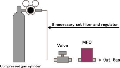
● We recommend providing a valve in front of the mass flow controller. By so doing, mass flow controller will set the flow, and open or close the valve. You can completely shut off if you do not shed gas. In addition, the flow rate is not changed on mass flow controller. The same set flow rate will be reproduced.
● Even if the flow rate is changed frequently during passing gas, we recommend providing a valve when you shut off gas completely.
■ Left, valve arrangement. (e.g.) |
To those who are new to Mass Flow Controllers
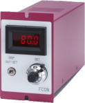
■ Flow rate setting of the mass flow controller is easy if you use the control power of the dedicated.
■ First, connect the mass flow controller body in the piping and hoses.
■ Adjust in required differential pressure (secondary side air release time: 50 - 300kPa) by the pressure regulator.
■ Connect the control power supply and the mass flow controller in the signal cable.
■ Then, turn on the power to connect the power cable of the control power supply.
■ FCON's control power supply [PA01S or PA01PS] : Set the front switch to SET, turn the volume and set the set flow rate.
■ When flowing gas, the set flow rate is automatically controlled.
● To change the flow rate, turn the volume of the control power supply and adjust the flow rate.
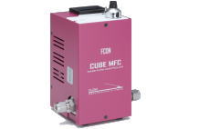
Mass Flow Controller [1000 Series]
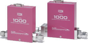 |
● Basic functions in pursuit of the unique technology.
● Flow range: F.S. 10ccm - 100LM
● Compact size.
● The suppression of Flow Surge at the start. (Requires more than 30 seconds of interval)
● Input & Output Signal : Analog (0-5VDC)
● It can be used in a wide range of fields including various facility equipment and experimental research. |
|
Go to Mass Flow Controller[1000 Series]page |